

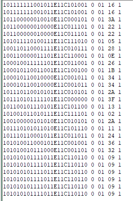
Test Output
Data Starts with 10
Next 13bits = Angle Data
Next 2bits after E = Error Data
Next 6bits after C = CRC Data (Inverted)
0 = Always '0' (Check Framing Error)
Next 2HEX = Error Count (Start From 01)
Next 2HEX = CRC Calculated
Next bit = Data Valid
Sampling Rate
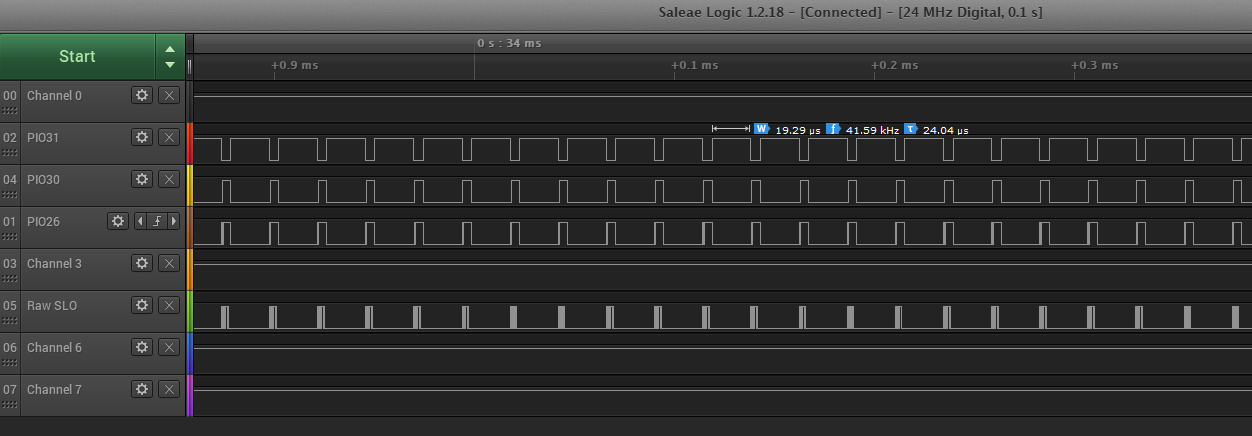
Sampling Frequency: 40kHz

Code
`timescale 1ns / 1ps
//////////////////////////////////////////////////////////////////////////////////
// Company: Monash Motorsport
// Engineer: Boon Jun
//
// Create Date: 11/06/2020 04:15:07 PM
// Design Name:
// Module Name: project3
// Project Name: BiSS FPGA
// Target Devices: Degilent CMod S7
// Tool Versions:
// Description:
//
// Dependencies:
//
// Revision:
// Revision-22Dec20
// Additional Comments: D:\workspace\project_3\project_3.runs\impl_1
//
//////////////////////////////////////////////////////////////////////////////////
module project3(
input clk,
input pio28,
input biss_slo,
input [1:0] btn,
output [3:0] led,
output pio26,
output pio30,
output pio31,
output biss_ma,
output led0_b,
output led0_g,
output led0_r,
output uart_tx
);
//=====LED Output====
assign led[3] = count_div67k[27]; //192MHz / 2^28 = 0.715Hz
assign led[0] = button_state[0];
assign led[1] = button_state[1];
assign led[2] = button_state[2];
assign led0_g = ~uart_busy;
//assign led0_b = button_state;
assign led0_r = ~biss_sampler_error;
//===================
//=====Digital Outout=====
assign pio26 = (sampler_state[2]);
assign pio30 = (sampler_state[1]);
assign pio31 = (sampler_state[0]);
assign uart_tx = uart_tx_buff;
assign biss_ma = biss_clk; //8MHz CLK
//========================
//====Clock Generator====
reg [30:0] count_div67k = 0;
reg [3:0] count_BiSS_CLK_HF = 0;
parameter [3:0] BISS_CLK_DIVIDER = 4'd6; //192MHz/ 6 = 32MHz
reg output_BiSS_CLK_HF = 0; //Will be BISS_CLK_DIVIDER/2 = 16MHz
reg output_BISS_DAT_HF = 0;
reg [13:0] uart_clk_count = 0;
parameter [13:0] UART_CLK_PERIOD = 14'd10000; //192MHz/10000 = 19.2kHz
reg output_uart_clk = 0;
reg [15:0] clk_slo_delay = 0;
reg [15:0] clk_slo_delay_buff;
always @ (posedge(clk_192MHz)) begin //Trigger at 192MHz (5.208ns)
count_div67k <= count_div67k + 1;
count_BiSS_CLK_HF = count_BiSS_CLK_HF + 1;
output_BISS_DAT_HF = ~output_BISS_DAT_HF;
uart_clk_count = uart_clk_count + 1;
if(count_BiSS_CLK_HF == BISS_CLK_DIVIDER) begin
count_BiSS_CLK_HF <= 0;
output_BiSS_CLK_HF <= ~output_BiSS_CLK_HF;
end
if(uart_clk_count == UART_CLK_PERIOD) begin
uart_clk_count <= 0;
output_uart_clk <= ~output_uart_clk; //Frequency 9600bit/s
end
if((sampler_state < 3'd4) && (transmission_count != 0)) clk_slo_delay <= clk_slo_delay + 1;
else if(sampler_state == 3'd4) clk_slo_delay_buff <= clk_slo_delay;
else if(sampler_state == 3'd0) clk_slo_delay <= 0;
end
//=========================
//====Input Debounce=========
reg [3:0] debounce_count;
reg [2:0] button_prev_state;
reg [2:0] button_state; //1 for Pressed, 0 for not Pressed
wire [2:0] button_raw_state = {btn[1],btn[0],~pio28};
parameter [3:0] DEBOUNCE_CONST = 4'd15;
always @ (posedge (count_div67k[17])) begin //Trigger at 192MHz / 2^18 = 732Hz
if(button_raw_state != button_prev_state) debounce_count = 4'b0;
else if(debounce_count < DEBOUNCE_CONST) debounce_count = debounce_count + 4'b1;
else button_state = button_raw_state;
button_prev_state = button_raw_state;
end
//===========================
//=====BiSS Sampler==== //Runs at 96MHz
parameter FULL_PERIOD = 4'd12;
parameter HALF_PERIOD = 4'd6;
reg [3:0] clock_cycle_count = 0;
reg [2:0] sampler_state;
reg [31:0] biss_message;
reg [4:0] biss_message_count = 0;
reg data_ready=0;
reg ready_to_transfer = 0;
reg [5:0] transfer_id = 0;
reg biss_sampler_error = 0;
reg [7:0] biss_char [0:31];
always @(posedge(output_BISS_DAT_HF)) begin //Trigger at 96MHz (10.42ns Period)
if((transmission_count != 0) && (sampler_state == 3'd0) && (ready_to_transfer == 1))
begin
sampler_state = 3'd1;
ready_to_transfer = 0;
end
case (sampler_state)
3'd0: begin
ready_to_transfer <= 1;
biss_message_count <= 5'd0;
clock_cycle_count <= HALF_PERIOD;
end
3'd1: begin
if(biss_slo == 0) begin
biss_sampler_error <= 1;
sampler_state <= 3'd0;
end
else sampler_state <= 3'd2;
end
3'd2: begin
if(biss_slo == 0) begin
sampler_state <= 3'd3; //Latch First Signal
biss_sampler_error <= 0;
end
else if(transmission_count == 0) begin
biss_sampler_error <= 1;
sampler_state <= 3'd0;
end
end
3'd3: begin
if(biss_slo == 1) sampler_state <= 3'd4;//Synchronize
end
3'd4: begin //Collect 32bit of Data
clock_cycle_count = clock_cycle_count - 4'd1;
if(clock_cycle_count == 0)
begin
biss_message[biss_message_count] = biss_slo;
clock_cycle_count = FULL_PERIOD;
if(biss_message_count == 5'd31) sampler_state = 3'd5;
else biss_message_count = biss_message_count + 1;
end
end
3'd5: begin
if(biss_slo == 1)
begin
transfer_id <= transfer_id + 1;
sampler_state <= 3'd0; //Ready for new batch
end
end
endcase
end
//=====================
//=====ERROR Logger======
reg [7:0] error_count;
always @ (posedge ready_to_transfer) begin //Transfer Ended
if((biss_message[15] != 1) || (biss_message[16] != 1)) error_count = error_count + 1;
end
wire [7:0] error_m_sig,error_l_sig;
wire [7:0] test1,test2;
byte_to_Char b2c_1 (.iByte(error_count),.oCharLHS(error_m_sig),.oCharRHS(error_l_sig));
byte_to_Char b2c_2 (.iByte({2'd0,crc_output}),.oCharLHS(test1),.oCharRHS(test2));
wire [7:0] delay_1,delay_2,delay_3,delay_4;
byte_to_Char b2c_3 (.iByte(clk_slo_delay_buff[7:0]),.oCharLHS(delay_3),.oCharRHS(delay_4));
byte_to_Char b2c_4 (.iByte(clk_slo_delay_buff[15:8]),.oCharLHS(delay_1),.oCharRHS(delay_2));
//=======================
//===CRC Checker===
wire [5:0] crc_output;
wire crc_validity;
crc_check(.iRaw(biss_message[16:2]),.iCRC(biss_message[22:17]),.oRaw_CRC(crc_output),.oValid(crc_validity));
//=================
//=========Send Pulse - BiSS CLK/MA=======
reg biss_clk = 1;
reg button0_prev_state;
reg [4:0] transmission_count =5'b0;
parameter [4:0] PULSE_TO_SEND = 5'd30;
always @ (posedge output_BiSS_CLK_HF) begin //Trigger at 16MHz
if((((button_state[0] == 1'b1) && (button0_prev_state == 1'b0))||button_state[1] == 1'b1) && (ready_to_transfer == 1)) transmission_count = PULSE_TO_SEND; //Set to transmit 30 Pulse
if((biss_clk == 1'b1) && (transmission_count != 5'd0))
begin
transmission_count = transmission_count - 5'd1; //Pulse Decay
biss_clk = 1'b0;
end
else if(biss_clk == 1'b0)
begin
biss_clk = 1'b1;
end
button0_prev_state = button_state[0];
end
//=========================================
//=====UART====
reg uart_reset = 1;
reg [7:0] uart_message [0:127];
wire [6:0] message_add;
wire uart_tx_buff;
wire uart_busy;
reg [3:0] uart_setup_state = 0;
reg [5:0] transfer_id_prev = 0;
reg [6:0] uart_message_count = 0;
parameter [7:0] char_zero = 8'd48;
always @(posedge(output_uart_clk)) begin //9600Hz
if((transfer_id != transfer_id_prev) && (ready_to_transfer == 1) && (uart_setup_state == 0)) begin
uart_setup_state = 1;
transfer_id_prev = transfer_id;
// uart_message_count = 0;
// repeat(30) begin
// uart_message[uart_message_count] = biss_message[uart_message_count] + char_zero;
// uart_message_count = uart_message_count + 1;
// end
// uart_message[0:30] = biss_char[0:30];
// {>>{uart_message}} = biss_char;
uart_message[00] <= biss_message[00] + char_zero;
uart_message[01] <= biss_message[01] + char_zero;
uart_message[02] <= 8'h41; //'A'
uart_message[03] <= biss_message[02] + char_zero;
uart_message[04] <= biss_message[03] + char_zero;
uart_message[05] <= biss_message[04] + char_zero;
uart_message[06] <= biss_message[05] + char_zero;
uart_message[07] <= biss_message[06] + char_zero;
uart_message[08] <= biss_message[07] + char_zero;
uart_message[09] <= biss_message[08] + char_zero;
uart_message[10] <= biss_message[09] + char_zero;
uart_message[11] <= biss_message[10] + char_zero;
uart_message[12] <= biss_message[11] + char_zero;
uart_message[13] <= biss_message[12] + char_zero;
uart_message[14] <= biss_message[13] + char_zero;
uart_message[15] <= biss_message[14] + char_zero;
uart_message[16] <= 8'h45; //'E'
uart_message[17] <= biss_message[15] + char_zero;
uart_message[18] <= biss_message[16] + char_zero;
uart_message[19] <= 8'h43; //'C'
uart_message[20] <= biss_message[17] + char_zero;
uart_message[21] <= biss_message[18] + char_zero;
uart_message[22] <= biss_message[19] + char_zero;
uart_message[23] <= biss_message[20] + char_zero;
uart_message[24] <= biss_message[21] + char_zero;
uart_message[25] <= biss_message[22] + char_zero;
uart_message[26] <= 8'h20; //Space Bar
uart_message[27] <= biss_message[23] + char_zero;
uart_message[28] <= 8'h20; //Space Bar
uart_message[29] <= error_m_sig;
uart_message[30] <= error_l_sig;
uart_message[31] <= 8'h20; //Space Bar
uart_message[32] <= test1;
uart_message[33] <= test2;
uart_message[34] <= crc_validity + char_zero;
uart_message[35] <= 8'h20; //Space Bar
uart_message[36] <= delay_1;
uart_message[37] <= delay_2;
uart_message[38] <= delay_3;
uart_message[39] <= delay_4;
uart_message[40] <= 8'h0D;
uart_message[41] <= 8'h0A;
uart_message[42] <= 8'h00;
// uart_message[0] = biss_message[7:0];
// uart_message[1] = biss_message[15:8];
// uart_message[2] = biss_message[23:16];
// uart_message[3] = biss_message[31:24];
//// uart_message[4] = 8'h0D; //Carriage Return
//// uart_message[5] = 8'h0A; //New Line
// uart_message[4] = 8'hFF;
// uart_message[5] = 8'hFF;
// uart_message[6] = 8'hFF;
// uart_message[7] = 8'hFF;
// uart_message[8] = 8'hFF;
// uart_message[9] = 8'hFF;
// uart_message[10] = 8'hFF;
// uart_message[11] = 8'hFF;
// uart_message[12] = 8'hFF;
// uart_message[13] = 8'hFF;
// uart_message[14] = 8'hFF;
// uart_message[15] = 8'hFF;
end
case(uart_setup_state)
1: begin
uart_reset = 0;
if(uart_busy == 1) uart_setup_state = 2;
end
2: begin
if(uart_busy == 0) begin
uart_setup_state = 0;
uart_reset = 1;
end
end
endcase
end
Uart_transmission trans1(.iClk(output_uart_clk), .iRst(uart_reset), .iMessage(uart_message[message_add]),.oTxUA(uart_tx_buff),.oBusy(uart_busy),.oAdd(message_add));
//=============
//=======Clock Upscale=======
wire clk_192MHz;
wire reset;
assign reset = 0;
clk_gen_wrapper clk_gen_1(.clk_in1(clk), .clk_out1(clk_192MHz), .reset_in1(reset)); //Output 192MHz Clock
//===========================
endmodule
////////////////////////////////////////////////////////////////////////////////
// Copyright (C) 1999-2008 Easics NV.
// This source file may be used and distributed without restriction
// provided that this copyright statement is not removed from the file
// and that any derivative work contains the original copyright notice
// and the associated disclaimer.
//
// THIS SOURCE FILE IS PROVIDED "AS IS" AND WITHOUT ANY EXPRESS
// OR IMPLIED WARRANTIES, INCLUDING, WITHOUT LIMITATION, THE IMPLIED
// WARRANTIES OF MERCHANTIBILITY AND FITNESS FOR A PARTICULAR PURPOSE.
//
// Purpose : synthesizable CRC function
// * polynomial: x^6 + x^1 + 1
// * data width: 15
//
// Info : tools@easics.be
// http://www.easics.com
////////////////////////////////////////////////////////////////////////////////
module crc_check(iRaw,iCRC,oRaw_CRC,oValid);
input [14:0] iRaw;
input [5:0] iCRC;
output reg [5:0] oRaw_CRC;
output reg oValid;
reg [14:0] raw_data_flipped;
reg [5:0] crc_flipped;
always @(*) begin
raw_data_flipped[00] <= iRaw[14];
raw_data_flipped[01] <= iRaw[13];
raw_data_flipped[02] <= iRaw[12];
raw_data_flipped[03] <= iRaw[11];
raw_data_flipped[04] <= iRaw[10];
raw_data_flipped[05] <= iRaw[09];
raw_data_flipped[06] <= iRaw[08];
raw_data_flipped[07] <= iRaw[07];
raw_data_flipped[08] <= iRaw[06];
raw_data_flipped[09] <= iRaw[05];
raw_data_flipped[10] <= iRaw[04];
raw_data_flipped[11] <= iRaw[03];
raw_data_flipped[12] <= iRaw[02];
raw_data_flipped[13] <= iRaw[01];
raw_data_flipped[14] <= iRaw[00];
crc_flipped[0] <= iCRC[5];
crc_flipped[1] <= iCRC[4];
crc_flipped[2] <= iCRC[3];
crc_flipped[3] <= iCRC[2];
crc_flipped[4] <= iCRC[1];
crc_flipped[5] <= iCRC[0];
end
always @(*) begin
oRaw_CRC = nextCRC6_D15(raw_data_flipped,6'd0);
if(~crc_flipped == oRaw_CRC) oValid = 1;
else oValid = 0;
end
function [5:0] nextCRC6_D15;
input [14:0] Data;
input [5:0] crc;
reg [14:0] d;
reg [5:0] c;
reg [5:0] newcrc;
begin
d = Data;
c = crc;
newcrc[0] = d[12] ^ d[10] ^ d[6] ^ d[5] ^ d[0] ^ c[1] ^ c[3];
newcrc[1] = d[13] ^ d[12] ^ d[11] ^ d[10] ^ d[7] ^ d[5] ^ d[1] ^ d[0] ^ c[1] ^ c[2] ^ c[3] ^ c[4];
newcrc[2] = d[14] ^ d[13] ^ d[12] ^ d[11] ^ d[8] ^ d[6] ^ d[2] ^ d[1] ^ c[2] ^ c[3] ^ c[4] ^ c[5];
newcrc[3] = d[14] ^ d[13] ^ d[12] ^ d[9] ^ d[7] ^ d[3] ^ d[2] ^ c[0] ^ c[3] ^ c[4] ^ c[5];
newcrc[4] = d[14] ^ d[13] ^ d[10] ^ d[8] ^ d[4] ^ d[3] ^ c[1] ^ c[4] ^ c[5];
newcrc[5] = d[14] ^ d[11] ^ d[9] ^ d[5] ^ d[4] ^ c[0] ^ c[2] ^ c[5];
nextCRC6_D15 = newcrc;
end
endfunction
endmodule
//======Convert Byte to 2 Char in HEX Form=====
module byte_to_Char(iByte,oCharLHS,oCharRHS);
input [7:0] iByte;
output reg [7:0] oCharLHS,oCharRHS;
always @(*) begin
if(iByte[3:0] >= 10) oCharRHS = iByte[3:0] - 8'd10 + 8'h41;
else oCharRHS = iByte[3:0] + 8'h30;
if(iByte[7:4] >= 10) oCharLHS = iByte[7:4] - 8'd10 + 8'h41;
else oCharLHS = iByte[7:4] + 8'h30;
end
endmodule
//===============================================
module Uart_transmission(iClk,iRst, iMessage, oTxUA, oBusy, oAdd);
input iClk, iRst;
input [7:0] iMessage;
output oTxUA;
output oBusy;
output [6:0] oAdd;
assign oTxUA = uart_tx_buff_f;
assign oAdd = message_count;
assign oBusy = uart_busy;
//=====UART TX=====
reg uart_busy;
reg prev_iRst;
reg[6:0] message_count=0;
reg [3:0] uart_state = 0;
reg uart_tx_buff_f = 1;
reg [7:0] uart_message_buffer;
always @(posedge(iClk)) begin
if(iRst == 1) uart_state = 0;
else if(iRst == 0 && prev_iRst == 1) begin
uart_state = 4'd1;
message_count = 7'd0;
end
case(uart_state)
0: begin //Idle State
uart_tx_buff_f = 1;
uart_busy = 0;
message_count = 7'd0;
end
1: begin //'0' Logic
uart_busy = 1;
uart_tx_buff_f = 0;
uart_message_buffer = iMessage;
message_count = message_count + 1;
uart_state = uart_state+1;
end
2,3,4,5,6,7,8,9: //Send Data
begin
uart_tx_buff_f = uart_message_buffer[uart_state-2];
uart_state = uart_state+1;
end
10: begin //Parity
uart_tx_buff_f = ~^uart_message_buffer; //Odd Parity
uart_state = uart_state+1;
end
11: begin //Stop Bit 1
uart_tx_buff_f = 1;
uart_state = uart_state+1;
end
12: begin
if((iMessage == 8'd0) ||(message_count == 7'd50)) uart_state = 4'd0;
else uart_state = 4'd1;
end
default:
begin
uart_state = 4'd0;
end
endcase
prev_iRst = iRst;
end
//=================
endmodule
Verilog