

Currently using BISS-C
MA - Clock - Master Clock
SLO - Data Output - Slave Out
The encoder has no input means unable to do bus configuration, only able to do point-to-point configuration
Possible implementation for multi-channel

Data SLO
SCDS (Single-Cycle Sensor Data)

Current BISS encoder
Data Value Length: 13bit Absolute position (S13 ... S0) (8192 Resolution)
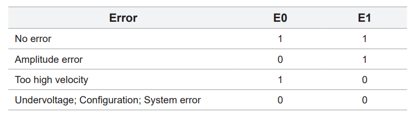
Flags: Error Bit (E1 E0)
CRC: Cyclic redundancy check data; polynomial 0x43; inverted bit output
Data Left Aligned
3 + 13 + 2 + 6 = 24bits
10MHz = 100ns
8MHz = 125ns
4MHz = 250ns
Total Time:
100ns = 2.4us
125ns = 3us
250ns = 6us
30kHz = 33uS
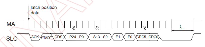
MA line is idle high. Communication is initiated with first falling edge. The encoder responds by setting SLO low on the second rising edge on MA. When the encoder is ready for the next request cycle it indicates this to the master by setting SLO high. The absolute position and CRC data is in binary format and sent MSB first.
From Renishaw
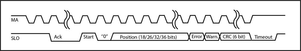
A typical request cycle proceeds as follows:
When idle, the master holds MA high. The encoder indicates it is ready by holding SLO high.
The master requests position acquisition by starting to transmit clock pulses on MA.
The encoder responds by setting SLO low on the second rising edge on MA.
After the “Ack” period is complete, the encoder transmits data to the master synchronised with the clock as shown in the diagrams above.
When all data has been transferred, the master stops the clock and sets MA high.
If the encoder is not yet ready for the next request cycle, it sets SLO low (the Timeout period).
When the encoder is ready for the next request cycle, it indicates this to the master by setting SLO high.