

Introduction
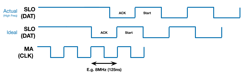
BiSS Waveform - Scope Signal + Investigation
FPGA Output
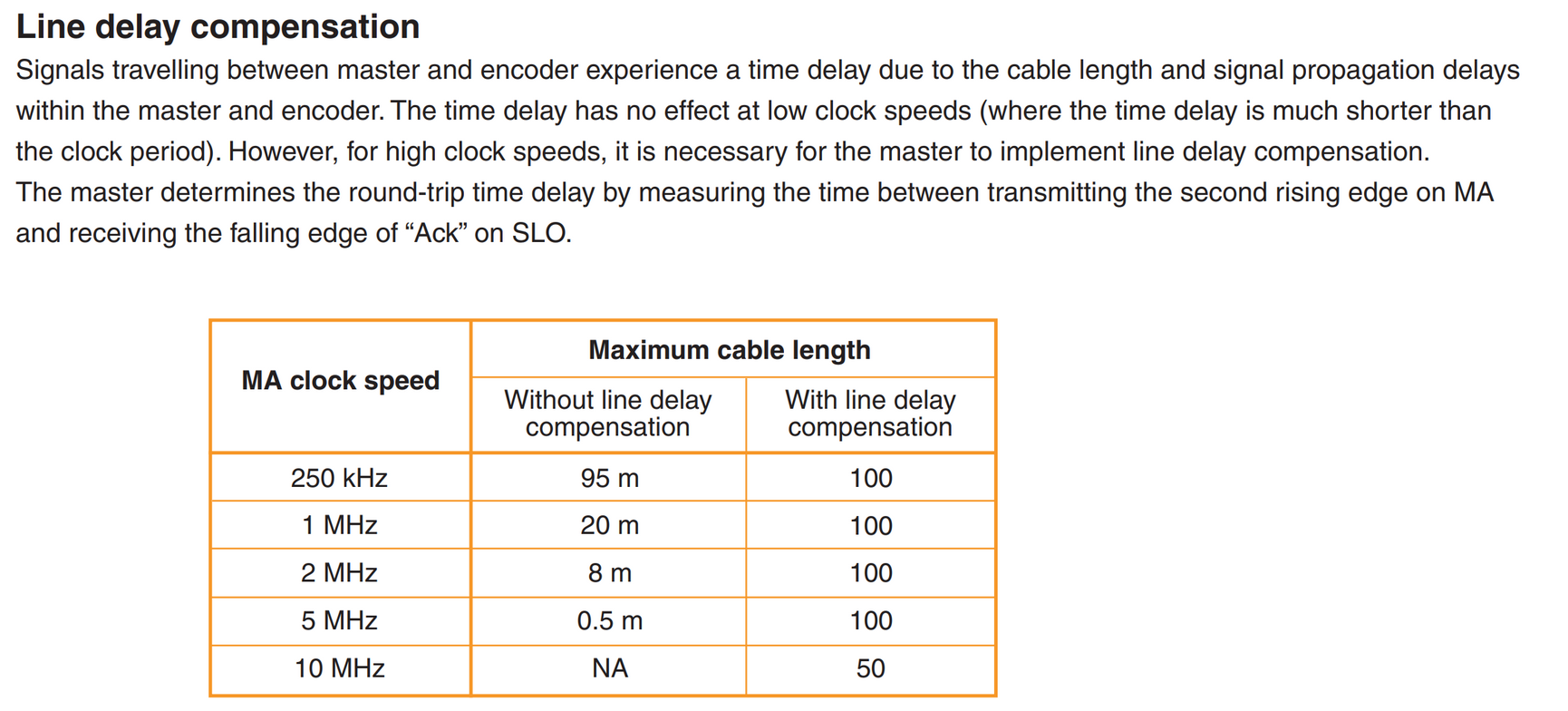
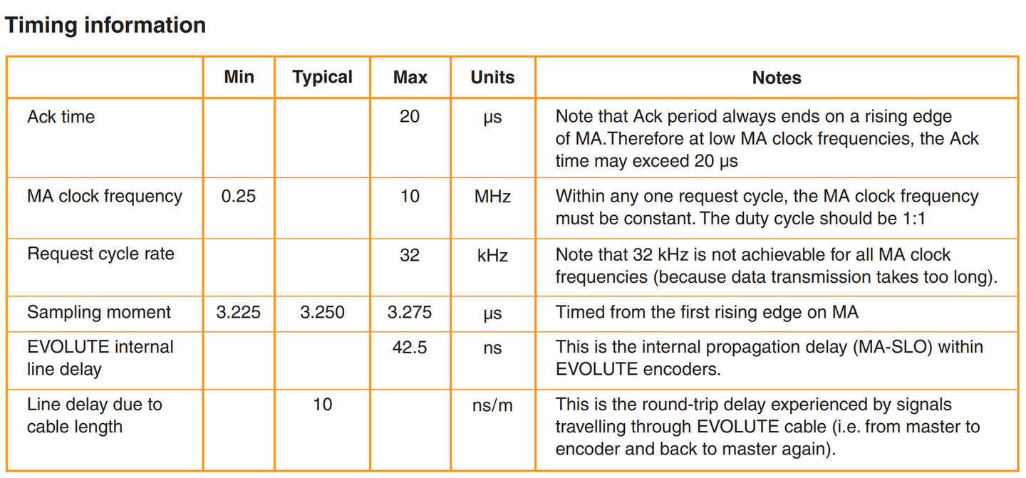
Delay
Visualization (Based on → Link)
Decode
Acquisition
RPM Output

CRC
Verilog CRC
Refresh Rate of RM44D05
Phase Synchronisation
GPIO123 goes high at start of switching cycle
GPIO123 goes low at end of switching cycle (~15us)
GPIO123 rising edge will start a countdown of (~42us (Tuneable)) for FPGA to start sampling BiSS Position
Expected Position Delay
SPI Packet Composition
<12:0> Position Data
<13> Parity (Odd Parity)
module ParityChecker(
input [7:0] bitt,
output ans
);
assign ans = ~^bitt;
endmodule
Verilog
<14> Error
When Error:
<0> Encoder E0
<1> Encoder E1
<3:2> FPGA biss_sampler_error_code
<15> CRC Invalid, use previous valid data
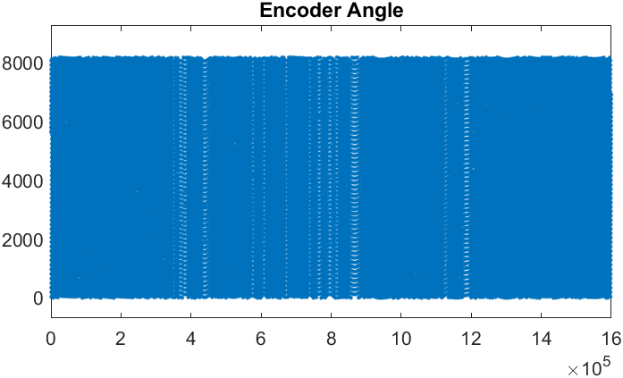
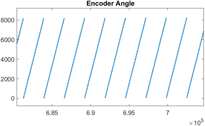
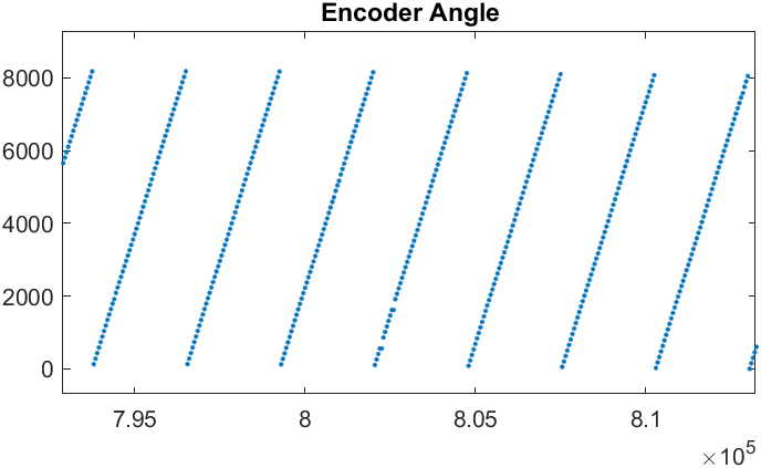
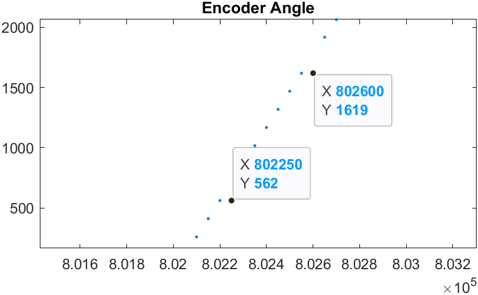
Logged Data Waveform (Fixed)
Error are not consistent, error likely caused by glitch
New update, fixed glitch by changing the sync sampling
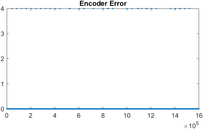

Error Code 4 == Encoder SLO line low at start
Data Error
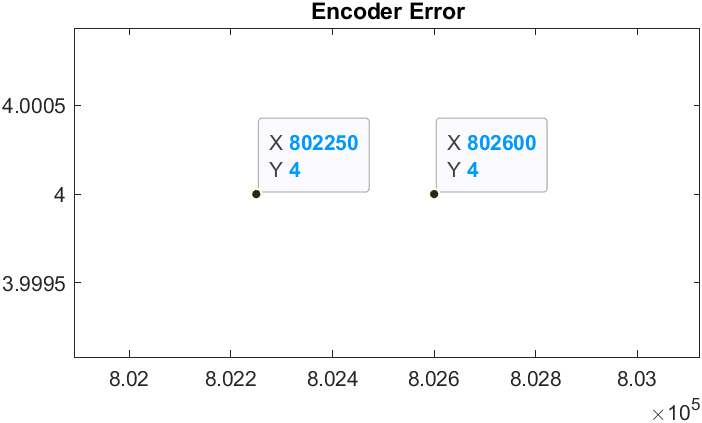
Error Rate: 41/32000 = 0.128%